Data Acquisition Device
Features summary:
1. Full-speed USB 2.0 communication.
2. Drivers available for Windows 2000/XP/Vista.
3. Embedded command interpreter.
4. 12 general purpose digital I/Os:P0,P1,P2,P3,P4,P5,P6,P7,P8,P9,Pa,Pb.
5. Analog Input Channel(10 bits ADC):ADC0 and ADC1, ADC Range [0:1023].
6. Pulse Width Modulation:One Channel, PWM Width Range [0:255].
7. Analog Output Channel: One Channel, DAC Range [0:255]
8. UART:TX and RX support.
9. Powers from USB.
10.Provide Visual Basic 6.0 Test Program Source Code.(VB 6 testing case)
USB data acquisition device control method is very easy for Windows XP / Vista operating system. The simplest way is through the virtual Com Port. Any existing software or programming environment that can send text string to a COM port will know how to talk to the USB data acquisition device. You can even perform simple tests with your favorite terminal emulator. The product needs to be assembled and soldered by yourself.
Four functional modules, I/O, ADC, PWM and UART are provided; the followings are the specifications for them.
USB Data Acquisition Device Pin definition:
Control Command Format:
(1) 12 Digital Input/Output Ports:
+out0=1# ………………send to USB_IO
+OUT0=1# ……………………Receive from USB_IO
+outa=0# ………………Send to USB_IO
+OUTa=0# ……………………Receive from USB_IO
+in6# ………………Send to USB_IO
+IN6=0# ………………………Receive from USB_IO
+ina# ………………Send to USB_IO
+INa=1# ………………………Receive from USB_IO
(2) Analog Input Channel:
10 bits ADC, The ADC Range [0:1023].
+adc0# ………………Send to USB_IO
+ADC0=0220# ………………………Receive from USB_IO
+adc1# ………………Send to USB_IO
+ADC1=1023# ………………………Receive from USB_IO
(3) Pulse Width Modulation(DAC function):
Frequency=2.9KHz, PWM Width Range [0:255].
+pwm=160# ………………Send to USB_IO (Width Range=160)
+OK# ………………………Receive from USB_IO
+pwm=009# ………………Send to USB_IO (Width Range=9)
+OK# ………………………Receive from USB_IO
(4) UART TX/RX:
1 Start bit + 8 Data bits + 1 Stop bit. The TX/RX Buffer = 32 bytes.
+rate=2# ………………Send to USB_IO (UART Rate=9600 bps)
+OK# ………………………Receive from USB_IO
Parameters

+txd=12345# ………………Send to USB_IO (TX: Send Data)
+OK# ………………………Receive from USB_IO
+rxd# ………………Send to USB_IO (RX: Receive Data)
+RXD=ABCDEFG# ………………………Receive from USB_IO
Installation drivers
Plug USB data acquisition device into USB port; if your OS is Windows, it will be detected automatically.You will see a pop-out window as the picture shown below.Click on “Install from a list or specific location”.
Set the installation path to CD_ROOT\inf
A security alert would come out; just click on “Continue Anyway”
The window will appear after the hardware installed done.
In Device Manager, you will see it. Please refer to following figure.
USB data acquisition device circuit:
The input of ADC1(OSC) and ADC0(VIN) are resistor dividers, R5/R7 and R6/R8 respectively. It means that you can control the ratio of resistor, manually. For example, R5/R7=10k/2k and the input voltage equals 5v, the ADC reads 0240 (For a 10-bit ADC, the range is 0000 - 1023).
The pwm function makes it very simple to generate a programmable control voltage. It is also possible to use the pwm outputs without any filtering, the pwm output connected directly.
A simple R-C filter will generate a clean, linearly varying analog voltage, and by changing this voltage at regular intervals, it is also possible to generate arbitrary waveforms.
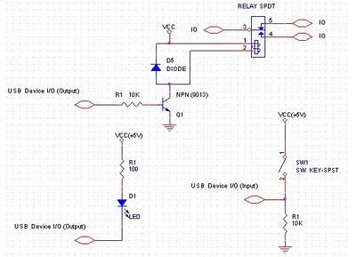
USB device reference I/O Circuit:
USB data acquisition device PCB:
USB data acquisition device outline:
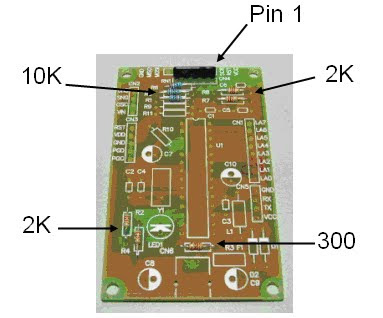
Steps for installation the components of USB data acquisition device:
1.Assemble resistance R1, R5, R6 (the 10K ohm), R3 (the 300 ohms), R2, R4, R7,R8 (the 2K ohm) and RN1 (the 4.7K ohm, attention installs Pin 1).
2.Assemble D1 and D2. (the 1N4148 diode, attention polarity).
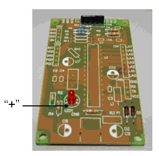
3.Assemble LED1 (LED, attention polarity)
4.Assemble capacity CAP1, CAP3 (100uF, attention polarity), CAP2 and CAP4 (10uF, attention polarity)
5.Assemble capacity C1, C3(0.1uF), C2 and C4(20pF).
6.Assemble quartz crystal Y1(12MHz), polymer resettable fuse FUSE1(0.5A) and inductance L1(220uH).
7.Assemble the USB connector and micro-controller U1.
8.Assemble CN1 (Pin Header 8 Pin), CN2 (Pin Header 4 Pin), CN4 (Pin Header 6 Pin) and CN5 (Pin Header 4 Pin).
Visual Basic 6.0 Test Program Source Code:
Private Declare Sub Sleep Lib "KERNEL32" (ByVal dwMilliseconds As Long)
'declare Sleep function
'=======================================================================
Dim DIO(11) As Integer ' Setup 12 Digital I/O
'Ture => out
'False => IN
'=======================================================================
Private Sub Form_Load()
Dim i As Integer
For i = 0 To 11
DIO(i) = 1
Next i
End Sub
'========================================================================
Private Sub Connect_Click()
If Connect.Caption = "Disconnect" Then
MSCom.InBufferCount = 0 'Clear MSCOM INPUT Buffer
MSCom.CommPort = COM_Number.Text
MSCom.Settings = "1152000,n,8,1"
MSCom.PortOpen = True
' MSCom.InputMode = comInputModeBinary
Connect.Caption = "Connect OK"
Timer1.Enabled = True 'Timer=0.1S (ADC0 & ADC1)
MSCom.Output = "+pwm=128#"
Sleep 10
MSCom.InBufferCount = 0 'Clear MSCOM INPUT Buffer
Else
Connect.Caption = "Disconnect"
Timer1.Enabled = False
MSCom.PortOpen = False
End If
End Sub
'=========================================================================
Private Sub END_Click()
End ' END Program
End Sub
'=========================================================================
Private Sub Op_48_Click() '4800 bps
MSCom.Output = "+rate=1#" 'command format
End Sub
Private Sub Op_96_Click() '9600 bps
MSCom.Output = "+rate=2#" 'command format
End Sub
Private Sub Op_1152_Click() '115200 bps
MSCom.Output = "+rate=3#" 'command format
End Sub
'=========================================================================
Private Sub RX_Click()
Dim SS As String
Dim i, j As Integer
DoEvents
RX_Text.Text = "" ' Clear Buffer
MSCom.InBufferCount = 0 ' Clear MSCOM INPUT Buffer
MSCom.Output = "+rxd#" ' command format
Sleep 100
j = MSCom.InBufferCount ' Receive Byte Counter
SS = MSCom.Input ' UART Input
RX_Text.Text = SS
End Sub
'=========================================================================
Private Sub Timer1_Timer() 'Timer=0.2S (ADC0 & ADC1)
Dim i, j As Integer
Dim SS As String
DoEvents
ADC0.Text = "" ' Clear
MSCom.InBufferCount = 0 ' Clear MSCOM INPUT Buffer
MSCom.Output = "+adc0#" ' command format
Sleep 100
j = MSCom.InBufferCount ' Receive Byte Counter
SS = MSCom.Input ' UART Input
ADC0.Text = SS
ADC1.Text = "" ' Clear
MSCom.InBufferCount = 0 ' Clear MSCOM INPUT Buffer
MSCom.Output = "+adc1#" ' command format
Sleep 100
j = MSCom.InBufferCount ' Receive Byte Counter
SS = MSCom.Input ' UART Input
ADC1.Text = SS
End Sub
'=========================================================================
Private Sub TX_Click()
TX = Red
DoEvents
MSCom.Output = "+txd=" & TX_Text.Text & "#" ' command format
'+txd=123456789abcdef#
End Sub
'========================================================================
' 12 Digital Input/Output Ports
'========================================================================
Private Sub Setup_Click()
Dim i As Integer
Dim SS As String
'********** out command **********
If DIO(0) = 1 Then
MSCom.Output = "+out0=" & D0.Text & "#"
End If
If DIO(1) = 1 Then
MSCom.Output = "+out1=" & D1.Text & "#"
End If
If DIO(2) = 1 Then
MSCom.Output = "+out2=" & D2.Text & "#"
End If
If DIO(3) = 1 Then
MSCom.Output = "+out3=" & D3.Text & "#"
End If
If DIO(4) = 1 Then
MSCom.Output = "+out4=" & D4.Text & "#"
End If
If DIO(5) = 1 Then
MSCom.Output = "+out5=" & D5.Text & "#"
End If
If DIO(6) = 1 Then
MSCom.Output = "+out6=" & D6.Text & "#"
End If
If DIO(7) = 1 Then
MSCom.Output = "+out7=" & D7.Text & "#"
End If
If DIO(8) = 1 Then
MSCom.Output = "+out8=" & D8.Text & "#"
End If
If DIO(9) = 1 Then
MSCom.Output = "+out9=" & D9.Text & "#"
End If
If DIO(10) = 1 Then
MSCom.Output = "+outa=" & D10.Text & "#"
End If
If DIO(11) = 1 Then
MSCom.Output = "+outb=" & D11.Text & "#"
End If
Sleep 100 'Delay time
MSCom.InBufferCount = 0 'Clear MSCOM INPUT Buffera1233
'*********** in command **********
If DIO(0) = 0 Then
MSCom.InBufferCount = 0 ' Clear MSCOM INPUT Buffer
MSCom.Output = "+in0#"
Sleep 10
SS = MSCom.Input ' UART Input
D0.Text = SS
End If
If DIO(1) = 0 Then
MSCom.InBufferCount = 0 ' Clear MSCOM INPUT Buffer
MSCom.Output = "+in1#"
Sleep 10
SS = MSCom.Input ' UART Input
D1.Text = SS
End If
If DIO(2) = 0 Then
MSCom.InBufferCount = 0 ' Clear MSCOM INPUT Buffer
MSCom.Output = "+in2#"
Sleep 10
SS = MSCom.Input ' UART Input
D2.Text = SS
End If
If DIO(3) = 0 Then
MSCom.InBufferCount = 0 ' Clear MSCOM INPUT Buffer
MSCom.Output = "+in3#"
Sleep 10
SS = MSCom.Input ' UART Input
D3.Text = SS
End If
If DIO(4) = 0 Then
MSCom.InBufferCount = 0 ' Clear MSCOM INPUT Buffer
MSCom.Output = "+in4#"
Sleep 10
SS = MSCom.Input ' UART Input
D4.Text = SS
End If
If DIO(5) = 0 Then
MSCom.InBufferCount = 0 ' Clear MSCOM INPUT Buffer
MSCom.Output = "+in5#"
Sleep 10
SS = MSCom.Input ' UART Input
D5.Text = SS
End If
If DIO(6) = 0 Then
MSCom.InBufferCount = 0 ' Clear MSCOM INPUT Buffer
MSCom.Output = "+in6#"
Sleep 10
SS = MSCom.Input ' UART Input
D6.Text = SS
End If
If DIO(7) = 0 Then
MSCom.InBufferCount = 0 ' Clear MSCOM INPUT Buffer
MSCom.Output = "+in7#"
Sleep 10
SS = MSCom.Input ' UART Input
D7.Text = SS
End If
If DIO(8) = 0 Then
MSCom.InBufferCount = 0 ' Clear MSCOM INPUT Buffer
MSCom.Output = "+in8#"
Sleep 10
SS = MSCom.Input ' UART Input
D8.Text = SS
End If
If DIO(9) = 0 Then
MSCom.InBufferCount = 0 ' Clear MSCOM INPUT Buffer
MSCom.Output = "+in9#"
Sleep 10
SS = MSCom.Input ' UART Input
D9.Text = SS
End If
If DIO(10) = 0 Then
MSCom.InBufferCount = 0 ' Clear MSCOM INPUT Buffer
MSCom.Output = "+ina#"
Sleep 10
SS = MSCom.Input ' UART Input
D10.Text = SS
End If
If DIO(11) = 0 Then
MSCom.InBufferCount = 0 ' Clear MSCOM INPUT Buffer
MSCom.Output = "+inb#"
Sleep 10
SS = MSCom.Input ' UART Input
D11.Text = SS
End If
End Sub
'=========================================================
Private Sub IO0_Click()
If DIO(0) = 1 Then
DIO(0) = 0: IO0.Caption = "in0"
Else
DIO(0) = 1: IO0.Caption = "out0"
D0.Text = "1"
End If
End Sub
Private Sub IO1_Click()
If DIO(1) = 1 Then
DIO(1) = 0: IO1.Caption = "in1"
Else
DIO(1) = 1: IO1.Caption = "out1"
D1.Text = "1"
End If
End Sub
Private Sub IO2_Click()
If DIO(2) = 1 Then
DIO(2) = 0: IO2.Caption = "in2"
Else
DIO(2) = 1: IO2.Caption = "out2"
D2.Text = "1"
End If
End Sub
Private Sub IO3_Click()
If DIO(3) = 1 Then
DIO(3) = 0: IO3.Caption = "in3"
Else
DIO(3) = 1: IO3.Caption = "out3"
D3.Text = "1"
End If
End Sub
Private Sub IO4_Click()
If DIO(4) = 1 Then
DIO(4) = 0: IO4.Caption = "in4"
Else
DIO(4) = 1: IO4.Caption = "out4"
D4.Text = "1"
End If
End Sub
Private Sub IO5_Click()
If DIO(5) = 1 Then
DIO(5) = 0: IO5.Caption = "in5"
Else
DIO(5) = 1: IO5.Caption = "out5"
D5.Text = "1"
End If
End Sub
Private Sub IO6_Click()
If DIO(6) = 1 Then
DIO(6) = 0: IO6.Caption = "in6"
Else
DIO(6) = 1: IO6.Caption = "out6"
D6.Text = "1"
End If
End Sub
Private Sub IO7_Click()
If DIO(7) = 1 Then
DIO(7) = 0: IO7.Caption = "in7"
Else
DIO(7) = 1: IO7.Caption = "out7"
D7.Text = "1"
End If
End Sub
Private Sub IO8_Click()
If DIO(8) = 1 Then
DIO(8) = 0: IO8.Caption = "in8"
Else
DIO(8) = 1: IO8.Caption = "out8"
D8.Text = "1"
End If
End Sub
Private Sub IO9_Click()
If DIO(9) = 1 Then
DIO(9) = 0: IO9.Caption = "in9"
Else
DIO(9) = 1: IO9.Caption = "out9"
D9.Text = "1"
End If
End Sub
Private Sub IOa_Click()
If DIO(10) = 1 Then
DIO(10) = 0: IOa.Caption = "ina"
Else
DIO(10) = 1: IOa.Caption = "outa"
D10.Text = "1"
End If
End Sub
Private Sub IOb_Click()
If DIO(11) = 1 Then
DIO(11) = 0: IOb.Caption = "inb"
Else
DIO(11) = 1: IOb.Caption = "outb"
D11.Text = "1"
End If
End Sub
'=======================================================================
' PWM Function
'=======================================================================
Private Sub Slider_Scroll()
Dim SS As String
DoEvents
If Slider.Value > 100 Then
SS = "+pwm=" & Right(Str(Slider.Value), 3) & "#"
ElseIf Slider.Value > 10 Then
SS = "+pwm=0" & Right(Str(Slider.Value), 2) & "#"
Else
SS = "+pwm=00" & Right(Str(Slider.Value), 1) & "#"
End If
MSCom.Output = SS
PWM_Label.Caption = "PWM Width: " & Slider.Value & "/255"
End Sub


沒有留言:
張貼留言